
Page 172 - CW E-Magazine (29-7-2025)
P. 172
Special Report
displayed on the LCD display. The ducer propagates through diff erent Angle beam testing, as its name
only requirement for getting correct boundaries, with some of it refl ecting implies, is used to locate cracks and
results is to calibrate the instrument back to the receiver when a boundary discontinuities that are tilted to the
with a sample of known thickness, or an anomaly (such as a crack) is longitudinal axis of the pipeline. This
prepared from the same material encountered. The refl ected sound method is crucial because defects that
as that of the material of the pipe. wave is then converted to an electrical are not parallel to the surface are usu-
Figure-7 shows thickness monitoring signal by the transducer and shown on ally undetected by straight beam test-
of tubes and pipes by ultrasonic a display screen. In addition to fl aws, ing due to their orientation to the sound
gauge called ‘D-Meter’(3). ultrasonic testing can also reveal other wave. Such angled cracks and defects
crucial information, such as size, typically occur in welds and structural
While there are several methods orientation, thickness and other criti- metal components due undue stresses.
available for detecting cracking cal features (Figure-8). During this technique, a common
defects in pipelines, ultrasonic testing angle beam (wedge) transducer or
techniques are perhaps the most How is ultrasonic technology used an immersion transducer is angled at
efficient and user friendly. As such, during crack inspection? the appropriate inclination to emit the
this technology should form an inte- Ultrasonic testing of cracks in pipe- sound wave into the pipeline.
gral part of a pipeline asset owner’s lines is conducted using two methods:
quality control and management straight beam testing and angle beam Using advanced ultrasonic techno-
processes. testing. logies to further improve inspection
safety
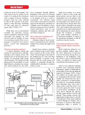
Ultrasonic technology explained Straight beam testing is typically While traditional ultrasonic ins-
A typical ultrasonic testing unit used to identify cracks or other defects pections methods address many of
consists of a pulser/receiver, ultrasonic that are parallel to the surface of the the safety defi ciencies of post-con-
transducer and a display device. The object. This technique is also ideal for struction hydrostatic testing, there are
pulser/receiver is an electronic device the identifi cation of voids and other limitations to this technology. Com-
capable of generating high-voltage porous locations. It operates on the plex features, such as tilted and hook
electrical pulses. The voltage from the principle that the sound energy will cracks, are diffi cult to detect using
pulser powers the transducer to create continue to propagate through the conventional inline ultrasonic tools.
high-frequency ultrasonic wave energy. medium until it encounters a boundary,
The sound produced by the trans- such as a crack. However, some ultrasonic technology
providers have developed propriety
technologies capable of addressing the
shortcoming of conventional ultrasonic
inspection techniques. NDT’s Eclipse
UCx solution, for example, uses a sen-
sor arrangement that provides deeper
insights into defects that were previ-
ously considered to be hard-to-detect.
In contrast to conventional ultrasonic
inline inspection tools, where only a
single signal is used, the Eclipse UCx
emits two signals that work in unison
to record defect information. As the
robot moves through the pipeline,
the dual signal interacts with the pipe
material. Upon striking a feature, one
signal bounces back to sensor A, while the
unshielded part of the signal continues
to travel through the material and is
Fig. 8: Principle of ultrasonic testing- Pulse echo technique with intercepted at sensor B. This specifi c
normal probe (a) & angle probe (b) arrangement makes it possible to
172 Chemical Weekly July 29, 2025
Contents Index to Advertisers Index to Products Advertised