
Page 168 - CW E-Magazine (29-7-2025)
P. 168
Special Report Special Report
Pipe inspection using radiography & retrofi tted onto conventional fi lm-based more than eight inches and there is in- Fluoroscopy, which is faster and safer
software simulation systems, eliminating the need for costly suffi cient clearance between pipelines than traditional radiography, can be
processing chemicals and equipment. running in a pipe rack. It is possible to used to quickly reveal corrosion and
Radiography for pipeline inspections scan pipelines of wider diameters by other internal pipeline defects.
Tangential fi lm-based radiography CR testing can be performed on the taking only a section of the pipeline in
is used to measure and monitor a pipe’s bends of the piping to check for cor- one shot. Consequently, multiple shots Benefi ts of DR
wall thickness and the possible pre- rosion or erosion. This is an accurate will be required to cover the full dia- DR is faster, safer (using up to 80%
sence of corrosion. During the examina- system but takes a lot of time to test meter of some pipelines, thus making the less radiation) and more effi cient than
tion of the pipeline, the steel pipes are each bend. Also, larger diameter pipes process more time consuming. Figure-5 conventional fi lm radiography, making
placed sideways to show its crossing require a cobalt source, hence making shows a schematic diagram of a PR setup it an ideal corrosion inspection tool for
section. The radiography beam is then use of this technique in a running plant showing a radiation source, insulated complex piping networks. Unlike other
exerted and projected onto a fi lm, thus is not possible for larger diameters. The pipeline, fi lm, and the radiographic inspections methods, DR does not re-
taking a direct measurement of the wall image in Figure-4 was taken by CR image showing the cross-section of in- quire the erection of scaff olding, access
thickness of the pipe. This is captured technique, showing corrosion depo- sulation thickness. The detailed radio- platforms and complex logistics. Addi-
on the fi lm and is measured and sits at the elbow of an insulated pipe. graph shows full diameter scan of the tionally, no mechanical probe adjust-
reviewed against an expected thickness. Wall thickness reduction is calculated insulated pipeline indicating suspected ments are needed over wide dimensional
using software. Before measurement, CUI locations as had been shown in ranges. Therefore, DR can result in
Pipeline inspections using software the software needs to be calibrated on Figure-2. CUI was indeed revealed signifi cantly less operational downtime
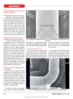
simulation and discrete tomography Fig. 3: Radiograph showing full diameter scan of an insulated pipeline showing suspected CUI reference wedges, such as a known-size when the insulation was opened. and yield faster results. Reduced down-
A software simulation using discrete locations steel ball or an identical pipe piece. time also translates to decreased cost
tomography can also be performed to techniques are: computed radiography material. The plate is then scanned by a Fluoroscopy/Real-Time Radiography of the radiography process.
reconstruct the pipe’s cross-section (CR), profi le radiography (PR), and fl u- laser, which produces a digital image Profi le Radiography (PR) (RTR)
with its corrosion defects. Discrete oroscopy/real-time radiography (RTR). that can be viewed, edited and shared PR is a proven technique to detect RTR works by converting invisible While DR can produce images
tomography can be applied although by a computer. the internal wall thickness reduction of X-rays into visible forms of light. X-ray with similar resolution to conventional
there are only two known factors in Computed Radiography (CR) small-bore piping. The technology can radiation is emitted on one side of the X-rays, the post-processing techniques
the object to be reconstructed: the pipe CR uses X-ray producing devices CR systems can be easily transpor- also be applied to fi nd CUI, provided material, where it penetrates the object applied to the digital image can im-
specimen itself and air. Software simu- similar to those found in conventional ted to the fi eld for on-site weld and wall that source-to-fi lm distance (SFD) is and is captured by sensors on the other prove overall quality. Image editing
lation is a cost-eff ective approach for X-ray testing; however, instead of fi lm, thickness profi le inspections for both suffi cient to cover the entire pipe dia- side. These sensors, which work by software can also be used to make other
presenting the data measurements and images are captured on reusable imag- insulated and uninsulated piping struc- meter in one shot. This may become fl uorescence, convert X-rays into light adjustments to the digital X-ray to
projections. It can be optimised using a ing plates coated with a phosphor-based tures. If needed, CR images can also be diffi cult when the pipeline diameter is to produce real-time digital images. improve the measuring and inspection
general optimisation strategy of simu- capabilities.
lated annealing. Figure-3 shows a re-
presentative radiograph of an insulated Other benefi ts of digital radio-
pipeline showing suspected corrosion graphy include:
under insulation (CUI) locations. Reduced exposure time;
Elimination of fi lm waste;
Detecting corrosion with digital radio- Improved data management; and
graphy (DR) Automated image archiving
One of the most popular imaging
techniques, X-ray inspection, has been Applications of DR
used in the oil and gas industry for over The non-destructive nature of DR
100 years. The constant evolution of makes it ideal for identifying defects in
this technology has led to a multitude sensitive pipeline infrastructure such as
of innovations. One of the latest deve- those found in the oil and gas industry.
lopments is DR, which refers to a group The level of detail that can be obtained
of advanced radiographic inspection allows it to be used for numerous ins-
techniques that use digital imaging as pection applications, including detect-
opposed to traditional fi lm. ing and measuring: uniform corrosion;
erosion corrosion; CUI; fl ow-assisted-
For pipeline corrosion inspections, Fig. 5: Schematic diagram of profi le radiography set up (the image shows cross-section of corrosion; corrosion under pipe sup-
three of the most common types of DR Fig. 4: CR radiograph showing corrosion deposits at the elbow of an insulated pipe insulation thickness ports; and welding corrosion.
168 Chemical Weekly July 29, 2025 Chemical Weekly July 29, 2025 169
Contents Index to Advertisers Index to Products Advertised